Wednesday 29 June 2011

April-June 2011

It's been a while between blogs, however much has been happening on  the layout.

The mains power to the layout and accessories, as well as the lighting controls, have been centralised on the end of the peninsula.
Centralised layout power and lighting controls

The amp meter is an indication of the total current draw of the layout and accessories from the main 240V supply.  The green neon lamp is an indication, when leaving, that nothing has been inadvertently left on (eg: soldering iron, hot glue gun, DCC booster etc) as it is easily seen from the exit doorway when you switch the room lights off.


All of the PSX circuit breakers (5) and auto-reverser (1)  have been wired into place, and the bus wires all terminated and labelled on a terminal strip.
PSX Circuit Breakers & Autoreverser


The booster has been temporarily wired in (I intend to hardwire the RRAmp meter when the layout track laying and dropper wiring is completed and tested).

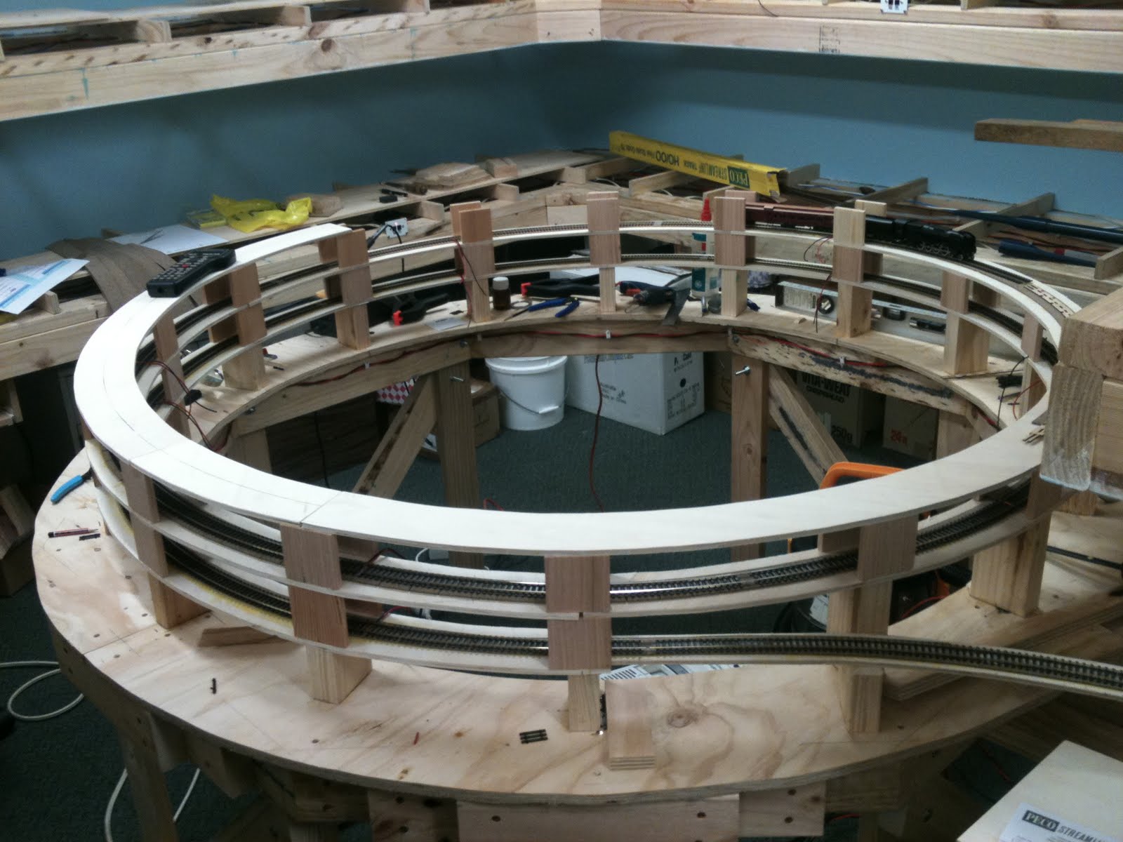
The lead-in track and the start of the inner helix
Track laying has begun, with the inner helix commencing construction, and is now 4 turns complete, only 4 more to go. Each loop of the helix is electrically gapped so that block detection can be used.  I will be using a Digitrax BDL168 to monitor 16 blocks, and give an indication via remote LED panel as to the travel/location of a train through the helix. There will also be viewing windows around the outside to allow visual contact for train crews.

The helix after 1 1/2 turns, with H220 and 1BCE as a test train

Halfway round the 4th turn

Saturday 2 April 2011

Cab Bus – March 2011

Using the internet, I tracked down a source of some universal throttle panels (UTP’s).  Despite the layout being wireless, it is useful to have points to connect either the wireless throttle (handset) or a wired throttle around the various parts of the layout.  There are 12 UTP’s on the layout.  I decided to install an LED on each panel to indicate both power available, as well as to be easily found in a darkened room running under night conditions. 

This required some PC board soldering skills, and a resistor, bi-colour LED and a wire bridge to be soldered to each of the 12 UTP boards.  The wire bridge was made from the excess wire cut off from the resistors, and installed so as to ground the face panel of the UTP.


The bi-colour LED bent and soldered in position (centre top)
It has been some time since I have tackled this type of soldering, but having the right tools, including variable temperature iron, quality solder and flux, the job was a breeze.  The only difficulty was viewing the tiny areas to be soldered.  A magnifying headset helped to bring everything into focus and large enough to see clearly. A pair of helping hands (third hands) helped to hold the PC board at the right angle whilst I soldered the components in place.


The added resistor soldered to the PC board

The small wire bridge soldered to the board insie the "U" bracket


Each UTP was then tested by applying 14V AC from the DCC track output to the LED connections on the UTP, and run for about 15 minutes.  It will be powered eventually by the accessory bus, which is really just a second 14V power bus.. Each UTP proved to be a success, no blown diodes, no magic smoke appearing, and no burnt fingers!

UTP in position and the LED working off 14V AC supply
As the length of the Cab bus will be more than 30m, I have powered every 3rd UTP with a 12V DC 1A power supply.  This provides power to the UTP and all downstream UTP’s until another power supply is plugged in downstream. This will help ensure that the signal from the booster is not lost as power losses occur over the cab bus, particularly when multiple throttles or handsets are plugged in.


The next job is to obtain some 3 pair cable and wire the UTP’s daisy chain fashion from the DCC Control Unit to the last UTP, where the Radio Aerial is connected in.

After evaluating several different systems, I chose the NCE Power Pro-R (radio) 5 Amp DCC system.  Combinations of wireless and wired throttles can be used with this system on the layout. The convenience of wireless and the features of this system led me to choose it as my preferred system.  Having used the NCE Radio system previously on Bill Black’s magnificent Sn3 layout - Vance Junction, I was comfortable with the use and operation of the NCE system on a layout running non-sound and sound equipped DCC locomotives and lighted passenger coaches.